Leak Checking:
1. Visual Inspection - Although oil seepage does not necessarily indicate leakage of refrigerant, it should be considered a sign that a leak may exist. Look for the following symptoms:
a) Oil seepage in shaft seal area (between clutch and compressor) – repairable.
b) Pinching or extrusion of front housing O-ring - non-repairable.
c) Oil around cylinder head (gaskets, service valves, fittings) - repairable.
d) Oil around oil plug – repairable.
e) Stripped threads – non-repairable.
f) Oil around crack in compressor body - non-repairable.
2. Soap Bubble Detection - Any leak showing up as bubbles on the compressor will require repair.
3. Shop Type Electronic Detectors
a) Ensure that the detector being used is sensitive to R134a refrigerant. Many leak detectors intended for R-12 cannot detect R134a leaks.
b) Use the leak detector in accordance with the manufacturer's instructions.
c) The leak rate at any portion of the compressor should not exceed 1.0oz./yr. Make sure that a suspected leak is an actual flow of refrigerant and not a small pocket of refrigerant trapped in a recess. Cleaning the suspect area with soap and water (never a solvent) or blowing off the area with compressed air can help confirm a suspected leak.
d) The leak check procedure should be in accordance with SAE J1628.
4. Leak Detection Dyes - The use of leak detection dyes is not recommended by Sanden as their chemical compositions are proprietary and their effects on Sanden oils and elastomers are unknown at this time.
Oil Level Measurement (In Vehicle):
Oil level in the compressor should be checked when a system component has been replaced, when an oil leak is suspected, or when it is specified as a diagnostic procedure.
1. Run the compressor for 10 minutes with the engine at idle.
2. Recover all refrigerant from the system, slowly so as not to lose any oil.
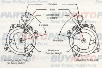
3. Determine the mounting angle of the compressor from horizontal (i.e., oil plug or adapter on top). This is most readily done by using a machinist's universal level, if access to the compressor permits it.
4. Remove the oil filler plug. Using a socket wrench on the armature retaining nut, turn the shaft clock wise until the counterweight is positioned as shown.
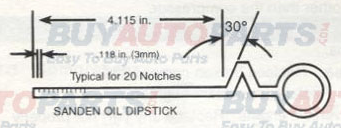
5. Insert the oil dipstick up to the stop, as shown in the figure above, with the angle pointing in the correct direction.

6. Remove dipstick and count the number of notches covered by oil. (See image above).
7. Add or subtract oil to meet the specifications shown in the table below:
Mounting angle
(Degrees)Acceptable oil level in incrementsSD5H14SD7H1503-55-7104-66-8205-77-9306-88-10407-99-11508-1010-12608-1011-13908-1016-18
8. Re-install the oil plug. Seat and O-ring must be clean and not damaged. Torque to 11-15 ft•lb (15-20 N•m, 150-200 kgf•cm).
Shaft Turning Smoothness Inspection:
1. If on vehicle, remove refrigerant from A/C system and disconnect hoses.
2. If on bench, uncap fittings.
3. Using a socket wrench on the armature retaining nut, turn the shaft clockwise only.
4. If severe rough spots or catches are felt while turning the shaft, the compressor has been damaged internally and must be replaced.
Clutch Inspection:
1. Measure the voltage at the clutch. Low voltage at the clutch may be due to poor ground or power connection, or problems with the vertical electrical system. Check for a tight fit of the field coil retaining snap ring.
2. Measure the current draw when the clutch is engaged. Normal current should be 3.6 - 4.2A at 12VDC.
a) Overcurrent - Short circuit within field coil or in compressor circuit.
b) No current - Open circuit.
If a short or open is found in the field coil, it must be replaced.
3 Air Gap
The clutch air gap should be 0.016-0.031 in (0.4 - 0.8 mm). Measure with a feeler gauge and adjust as advised by the manufacturer.
4. Suspected Clutch Rotor Bearing Noise
a) Remove drive belt.
b) With clutch disengaged, rotate pulley by hand. If excessive roughness or wobble is found, replace the clutch rotor assembly.
Unusual Noise Not Due to Compressor:
Unusual noises may be caused by components other than the compressor.
1. Compressor Mounting - Check for:
a) Loose belt - see belt tension specifications.
b) Broken bracket or compressor mounting ear. Replace broken component.
c) Missing, broken, or loose mounting bolts. Replace, reinstall, or tighten.
d) Flush fit of compressor to bracket and to vehicle engine. Replace any part that is not property fitted.
e) Loose or wobbling crankshaft pulley. Check for damage to pulley, incorrect center bolt torque or center bolt bottoming. Repair to vehicle manufacturer's specifications.
f) Bad idler pulley bearing. Replace if necessary.
2. Other Engine Components - Check for noise in:
a) Alternator bearing.
b) Air pump (if present).
c) Water pump bearing.
d) Valves.
e) Timing belt or chain.
f) Power steering pump (if present).
g) Loose engine mount bolts.
Unusual Noises Due to Compressor:
1. Suction pressure less than about 5 psig can cause an unusual noise. Charge the refrigerant to the proper amount and test it by applying heat to the evaporator to increase suction pressure.
2. Clutch Bearing.
See Clutch Inspection Section.
3. Oil Level.
Insufficient oil can cause unusual noise. See Oil Level Check Procedure.
4. Valve Noise.
Test for valve plate assembly failure as per the Valve Plate Test Procedure.
Valve Plate Test:
1. Suction or discharge valve breakage will cause a clacking sound at idle.
2. If the head gasket fails, the discharge pressure will be low and suction pressure will be high at idle.
3. Valve and gasket condition can be checked as follows:
a) Connect the gauge set to suction and discharge service valves.
b) Run the compressor for 5 minutes at idle and stop.
c) Observe time taken for the discharge pressure and suction pressure to equalize. If it is less than 2 minutes, in a TVX system, a valve or gasket may be damaged. A CCOT system will equalize more quickly.
