
Keyed Shaft Armature Removal:
(Note: Keyed shaft can be identified in that the holes for the armature plate spanner will have threads in them)
1. If armature dust cover is present, remove the 3 or 6 bolts holding it in place and remove cover. If auxiliary sheet metal pulley is present, remove the screws holding it in place. Then remove pulley.
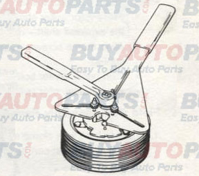
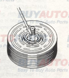
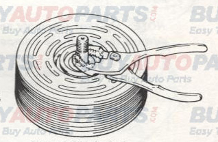
2. Insert pins of armature plate spanner into threaded holes of armature assembly.
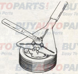
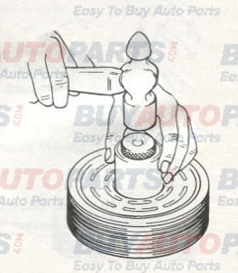
3. Hold armature assembly stationary while removing retaining nut with 3/4", 19mm, or 14mm socket wrench as appropriate.
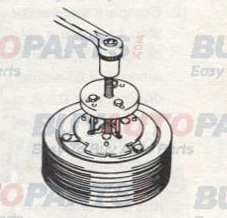
4. Remove armature assembly using puller. Thread 3 puller bolts into the holes in the armature assembly. Turn center screw clockwise until armature assembly comes loose.
5. If shims are above shaft key, remove them now. If shims are below shaft key, the key and bearing dust cover (if present) must be removed before the shims can be removed.
6. Remove bearing dust cover (if present). Use caution to prevent distorting cover when removing it.
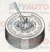
7. Remove shaft key by tapping loose with a flat blade screw-driver and hammer.
8. Remove shims. Use a pointed tool and a small screwdriver to prevent the shims from binding on the shaft.
Spline Shaft Armature Removal:
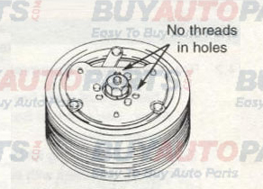
(Note: Spline shaft can be identified in that the holes for the armature plate spanner will not have threads in them.)
1. If armature dust cover is present, remove the 3 or 6 bolts holding it in place and remove cover. If auxiliary sheet metal pulley is present, remove the screws holding it in place. Then remove pulley.
2. Insert pins of armature plate spanner into threaded holes of armature assembly.
3. Hold armature assembly stationary while removing retaining nut with 3/4". 19mm, or 14mm socket wrench, as appropriate.
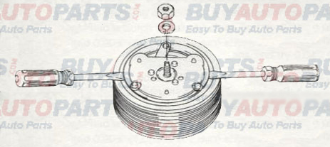
4. Lift off armature plate with fingers. If armature does not come off easily, spray an anti-seize oil into shaft to loosen the plate. Armature plate can also be loosened by gently prying between rotor and armature plate with two flat screw drivers.
5. If shims are above shaft key, remove them now. If shims are below shaft key, the key and bearing dust cover (if present) must be removed before the shims can be removed.
6. Remove bearing dust cover (if present). Use caution to prevent distorting cover when removing it.
7. Remove shims. Use a pointed tool and a small screwdriver to prevent the shims from binding on the shaft.
Rotor Assembly Removal:
1. If bearing dust cover has not been removed, remove it now. See step 6 of Keyed Shaft Armature Assembly Removal above.
2. If internal snap ring for bearing is visible above the bearing, remove it with internal snap ring pliers.
3. Remove rotor snap ring.
4. Remove shaft key.
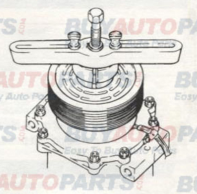
5. Remove rotor pulley assembly:
a) Insert the lip of the jaws into the snap ring groove.
b) Place rotor puller shaft protector (Puller set) over the exposed shaft.
c) Align thumb screws to puller jaws and finger tighten.
d) Turn puller center bolt clockwise using a socket wrench until rotor pulley is free.
Field Coil Assembly Removal:
1. Loosen lead wire clamp screw with #2 Phillips screw driver until wire(s) can be slipped out from under clamp.
2. Undo any wire connections on the compressor which would prevent removal of the field coil assembly.
3. Remove snap ring.
4. Remove the field coil assembly.
Field Coil Assembly Installation:
Reverse the steps in the section above (Field Coil Assembly Removal). Protrusion on underside of coil ring must match hole in front housing to prevent movement and correctly locate lead wire(s).
Rotor Assembly Installation:
1. Place compressor on support stand, supported at rear end of compressor. If the compressor must be clamped in a vise, clamp only on the mounting ears, never on the body of the compressor.
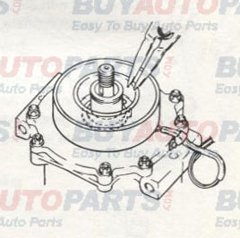
2. Set rotor squarely over the front housing boss.
3. Place the rotor installer ring into the bearing bore. Ensure that the edge rests only on the inner race of the bearing, not on the seal, pulley, or outer race of the bearing.
4. Place the driver into the ring and drive the rotor down into the front housing with a hammer or arbor press. Drive the rotor against the front housing step. A distinct change of sound can be heard when using a hammer to install the rotor.
5. Reinstall rotor bearing snap ring, if it has been removed, with internal snap ring pliers.
6. Reinstall rotor retaining snap ring with external snap ring pliers. If a bevel is present on the snap ring, it should face up (away from the body of the compressor).
7. Reinstall rotor bearing dust cover (if present) by gently tapping it into place.
Rotor Assembly Installation:
Armature Assembly Installation
1. Install shaft key with pliers.
2. Note: Keyed Shaft Only Install clutch shims. NOTE: Clutch air gap is determined by shim thickness. When installing a clutch on a used compressor, try the original shims first. When installing a clutch on a compressor that has not had a clutch installed before, first try 0.04", 0.02", and 0.004" (1.01 0.5, 0.1 mm) shims.
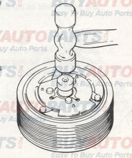
3. Keyed Shaft Only
Align keyway in armature assembly to shaft key. Using driver and a hammer or arbor press, drive the armature assembly down over the shaft until it bottoms on the shims. A distinct sound change will be noted if driving with a hammer.
4. Spline Shaft Only
Align slot in armature with locator tooth on shaft. Press armature towards rotor with hand until armature rests against the shims.
5. Replace retaining nut and torque to specification.
1/2-20: 20-25 ft•lb (27-34 N-m, 270-350 kg-cm).
M8: 11-15 ft•lb (15-21 N-rn, 150-210 kg-cm).
6. Check air gap with feeler gauge. Specification is 0.016" -0.031" (0.4 - 0.8mm). If gap is not even around the clutch, gently tap down at the high spots. If the overall gap is out of spec., remove the armature assembly and change the shims as necessary.
7. Replace armature dust cover (if used) and torque 3 or 6 bolts to specification below:
3 - 1/4-20 bolts (SD-5): 2-4 ft•lb (2-5 N-m, 25-50 kgf-cm).
6 - M5 bolts (SD-7): 5-8 ft•lb (7-11 N-m, 70-110 kgf-cm).
