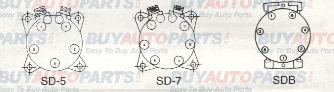
Replacement of Lip Type Shaft Seal (SD5H14, SD7B10, SD7H13, SD7H15):
Note: Lip seal assembly and felt ring must never be reused. Always replace these components.
1. Be sure all gas pressure inside the compressor has been relieved.
2. Remove armature dust cover (if used), armature assembly, rotor bearing dust cover (if used), shaft key, and clutch shims.
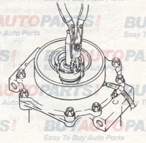
3. Insert the points of a pair of snap ring pliers into the holes of the felt ring retainer and pry out the retainer and felt ring.
4. Remove seal snap ring with internal snap ring pliers.
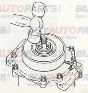
5. Use lip seal removal and installation tool to remove lip seal assembly. Twist the tool until the 2 lips on the tool engage the slots in the lip seal housing and pull the seal out with a twisting motion.

6. Clean out the shaft seal cavity thoroughly. Debris can be removed using a non-petroleum based solvent and a lint-free cloth. The area should then be blown out with clean, dry compressed air. Make sure all foreign material is completely removed.
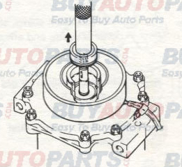
7. Place shaft seal protective sleeve over compressor shaft. Inspect the sleeve to ensure that it has no scratches and is smooth so that the lip seal will not be damaged. Make sure there is no gap between the end of the sleeve and the seal surface of the shaft.
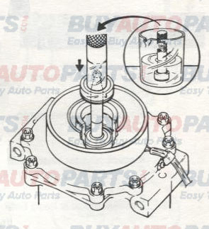
8. Engage the lips of the seal removal and installation tool with the slots in the new lip seal housing. Make sure the lip seal assembly, especially the O-ring, is clean. Dip the entire lip seal assembly, on the tool, into clean 5GS refrigerant oil. Make sure the seal assembly is completely covered with oil.
9. Install the lip seal over the shaft and press firmly to seat. Twist the tool in the opposite direction to disengage it from the seal and withdraw the tool.
10. Reinstall shaft seal snap ring with internal snap ring pliers. The beveled side should face up (outward / away from compressor body). Ensure that snap ring is completely seated in the groove. It may be necessary to tap the snap ring lightly to seat it in the groove.
11. Tap the new felt ring assembly into place.
12. Reinstall clutch shims. shaft key, rotor bearing dust cover (if used), and armature assembly.
13. Check and adjust air gap as necessary.
14. Reinstall armature dust cover (if used).
SERVICE OPER ATIONS CYLINDER HEAD/VALVE PLATE:
Cylinder Head Removal:
1. Be sure all internal compressor pressure has been relieved.
2. Inspect the cylinder head for fitting or thread damage. Replace if damaged.
3. Remove cylinder head bolts.
4. Use a small hammer and gasket scraper to separate the cylinder head from the valve plate. Be careful not to scratch the gasket surface of the cylinder head.
5. Carefully lift the cylinder head from the valve plate.
6. It is recommended that both the head gasket (between the cylinder head and the valve plate) and the block gasket (between the valve plate and cylinder block) be replaced any time the cylinder head is removed. However, if no service is required to the valve plate, it may be left in place. If the valve plate comes loose from the cylinder block, the block gasket must be replaced.
7. Carefully remove old head gasket from the top of the valve plate with the gasket scraper. Be careful not to disturb the valve plate to cylinder block joint if valve plate has been left in place. If valve plate comes loose from cylinder block, proceed to the next section, Valve Plate Removal, and replace block gasket.
Valve Plate Removal:
1. Using a small hammer and gasket scraper, carefully separate valve plate from the cylinder block. Be careful not to damage sealing surface of cylinder block.
2. Inspect reed valves and retainer. Replace valve plate assembly if any part is damaged.
3. Carefully remove any gasket material remaining on the valve plate, cylinder block or cylinder head. Do not damage sealing surfaces on components.
Valve Plate and Cylinder Head Installation:
1. Large gasket: OD of block gasket is 4-3/4" (120mm) and sealing face of block does not have a 4-1/2” (114.7mm) diameter step.
2. Small gasket: OD of gasket is 4-1/2" (114.7mm) and sealing face of the cylinder block has a 4-1/2" (114.7mm) diameter step.
3. Coat the new block gasket with clean 5GS refrigerant oil.
4. Install block gasket. Align new gasket to location pin holes and orifice(s). Notch (if present) should face same direction as oil plug or adapter.
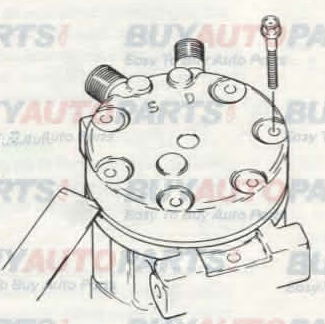
5. Place valve plate on cylinder block with discharge valve, retainer and nut facing up (away from cylinder block) and location pins properly located in holes.
6. Use vacuum pump and small tube to remove residual oil from each bolt hole. If this step is not performed, hydraulic pressure can be created when the cylinder head bolts are tightened. This pressure can break the cylinder block.
7. Coat the head gasket with clean 5GS refrigerant oil.
8. Install head gasket cover location pins, checking for correct orientation.
9. Install cylinder head.
10. Install cylinder head bolts and tighten them in a star pattern. Torque first to approximately 14 ft•lbf (19.6 N-m, 200 kgf-cm). then finish by torquing to 24-27 ft•lbf (32.4 - 36.3 N-m, 330-370 kgf-cm).