
Fuel System Foul Ups:
Are fuel pump returns from your shop increasing?
Understanding the root cause of technician diagnostic errors is the first step to successfully managing fuel system parts purchases and returns.
Over the years, vehicle fuel systems have become more complex as OEMs look to improve fuel burning and engine efficiency. And during that time, industry parts suppliers have noted that too many technicians are returning brand-new fuel pumps as defective, only to later discover that the root cause of the problem was a bad crankshaft sensor or fuel pump relay. As a technician, it's important that you keep up with modern fuel system technology. So, in order to avoid some of the most common technician mistakes in fuel system diagnosis, let's look at how some of today's most common fuel systems operate, and what some of the common failures and "silver bullet fixes" may be.
Inaccurate Level Readings:
A vehicle's fuel level must be accurately measured by the PCM in order to detect evaporative leaks. Consequently, newer fuel gauge configurations often incorporate a small module that may require as much as 20 minutes to compute the actual fuel level in the fuel tank. Without this particular bit of knowledge, many amateur technicians may assume that a tank is half-full of fuel when, in fact, it is not.
In addition, a fuel pump inlet strainer may be installed which may interfere with the travel on the fuel level sensor's float arm and causes an optimistic fuel level reading. Dented fuel tanks may also cause a false reading by pushing the fuel level sensor and fuel pump inlet filter above the remaining fuel level in the tank.
Whatever the case, the engine may be running out of gas simply because the instrument panel fuel gauge is providing a false reading.
Silently Working:
Under normal circumstances, most fuel pumps produce an audible noise for several seconds after the ignition switch is turned on. The relatively silent two-speed fuel pumps used in many import and domestic vehicles may, however, lead a technician to believe that the fuel pump is defective. Since the fuel pump speed in these applications is dependent upon the engine speed and load, a fuel pressure gauge should be used to determine if the pump is operating and if it's delivering the correct fuel pump pressure.
Of course, if the gauge doesn't show fuel pressure, we must remember how most fuel pumps are activated. When the ignition switch is turned on, the PCM activates the fuel pump for a few seconds to purge air from the fuel injectors and ensure proper fuel pressure for the engine's cranking cycle. Once the engine is cranked, the PCM "looks" for the presence of cranking speed and ignition triggering. Depending upon design, the PCM turns off the fuel pump if one or both of these inputs are missing. This specific sequence of events is necessary to prevent fuel from flooding an engine with an inoperative ignition system or the fuel pump from emptying the fuel tank during a serious accident.
Running the Relays:
A fuel pump relay is a high-current electrical switch operated by a low-current circuit in the PCM. As with all electrical switches, the contact points on the fuel pump relay eventually wear out, which reduces electric current flow to the fuel pump. Since this reduced current flow also reduces fuel pump speed, the engine may experience difficulty starting in cold weather, when battery voltage may be lower than normal.
No-Go Airflow:
A dirty or defective airflow sensor often causes stalling and surging complaints normally associated with a worn fuel pump. In the case of many imports, a signal from a vane-type air-flow sensor activates the fuel pump relay. If an air leak is present in the duct between the air-flow sensor and the throttle plate, the sensor won't activate the fuel pump during cranking, and the engine will fail to start. A simple test is to remove the air filter and manually open the airflow sensor vane a slight amount during cranking. If the fuel pump activates, the problem exists with the air duct, not the fuel pump.
Note: Clogged fuel filters also cause rapid fuel pump wear, which is why the fuel filter should be changed at 30,000-mile intervals and after installing a new fuel pump.
Finding Faulty Fuel Pumps:
Where do you begin your diagnosis, if you have an engine that cranks, but won't start?
If ignition and compression are both OK, that leaves fuel as the obvious culprit. Now the question is, what's wrong with the fuel delivery system? Well, the most likely causes are:
1. A dead fuel pump (could be the pump, pump relay or wiring circuit);
2. A plugged fuel filter;
3. Low fuel pressure (weak pump or restricted line); or
4. No pulse signal to injectors (bad injector relay or PCM driver circuit).
On most vehicles, the pump is energized by the PCM via a relay. The pump circuit also may be wired though an oil pressure switch and/or an inertia safety switch that kills the pump in case of an accident. Refer to a wiring diagram to find out what's involved before jumping to any conclusions.
Other electrical problems that can affect the pump include low voltage in the pump's power supply circuit or high resistance in the pump's ground circuit. Either may prevent the pump from running or spinning fast enough to generate normal fuel pressure.
Tests For Diagnosing A Faulty Fuel Pump:
Dead Head Pressure: This checks the maximum output pressure of the fuel pump. With the return line blocked, the pump should produce a pressure that's significantly higher than its normal operating pressure at idle. If the pressure rating does not go up with the return line blocked, the pump may not be able to deliver enough fuel at higher engine speeds. Possible causes include a worn pump, low voltage at the pump, a plugged fuel filter or inlet sock in the tank, an obstructed fuel line or almost empty fuel tank.
Fuel Volume Test: A fuel pump that delivers normal pressure may still cause drive-ability problems, if it can't deliver enough fuel volume to meet the engine's needs. A fuel volume test may therefore be the best way to evaluate the pump's condition.
A fuel volume test measures the volume of fuel delivered over a specified interval. This test can be done by connecting a fuel flow gauge into the fuel supply line, or by disconnecting the fuel return line from the fuel pressure regulator and connecting a hose from the regulator to a large container.
Caution: Make sure there are no open sparks or flames nearby while doing this test!
With the engine off, energize the pump and measure the volume of fuel delivered during the specified interval of time. As a rule, a good pump should deliver about one quart of fuel in 30 seconds.
Mis-diagnosis is the leading cause of fuel pump returns. If the engine runs but displays driveability symptoms that you suspect are fuel-related, attempt to eliminate possible causes by:
1. Checking the vehicle's OBD system;
2. Checking the ignition system;
3. Checking for vacuum leaks;
4. Checking the EGR & PCV systems; and
5. Running a power balance test.
Why Fuel Pumps Fail:
We all know that just replacing an electric fuel pump won't solve a no-fuel complaint because the pump itself is not only part of the fuel delivery system. A good technician must diagnose the no-fuel problem in order to properly service the vehicle. Here are a few of the most common reasons an electric fuel pump fails:
1. Loss of current or low voltage: The pump can't run without electricity, so anything that prevents current or voltage from reaching the pump will make it stop. This includes corroded, loose or broken wiring.
2. Dirt: Sediment or other debris in the tank can clog the pickup strainer, accelerate pump wear, damage the pump and/or cause the pump's check valve to stick open (which can cause a hard-starting condition due to loss of pressure when the engine is shut off). When dirt has caused a pump failure or if there appears to be a lot of dirt or sediment in the tank, the tank should be thoroughly cleaned to prevent a repeat failure.
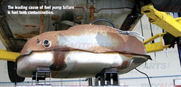
3. Rust: Corrosion inside the tank produces rust, which can flake off and plug up the pickup strainer and have the same damaging effects on the pump as dirt. Rust is caused by condensation, which occurs during cool, humid weather when the fuel tank is low. Keeping the tank full will minimize the formation of condensation. If the tank is badly rusted or leaking, it should also be replaced.
4. Normal wear: Most pumps are designed for long-term durability and performance, but their lifespan depends on the lubrication and cooling provided by the fuel itself. Frequent driving with a low fuel level may occasionally starve the pump for lubrication and cooling, which can lead to accelerated wear or even pump damage.
Failure Signs:
Noise may sometimes be an indication of excessive pump wear. Some pumps are inherently noisier than others, often because of the way in which they're mounted inside the tank. Noise also can be caused by a loose or missing rubber noise insulator around the pump, or physical contact with the bottom of the tank or tank baffles.
Fuel Pump Wiring Guide:
Instructions:
Read the instructions carefully before proceeding. If you don't, you may not be aware of personal injury and/or property damage risks you are taking.
Replacing Chassis Electrical Connector
Read the instructions carefully before proceeding. If you don't, you may not be aware of personal injury and/or property damage risks you are taking.
Warning: The fuel module assembly may contain liquid gasoline and gasoline vapors. Keep smoking materials, sparks and flames away from the repair area. If you don't, the gasoline could ignite and you could get burned.
Tools : Special Tool. Kent Moore J-38125-8 Crimping Tool (1-800-345-2233)
Determining the Correct Wiring Combination for Installing the New GT280 Connector:
1. Refer to the vehicle service manual or equivalent to remove the fuel module assembly.
2. Remove approximately 12 inches (330 mm) of tape and black plastic conduit from the vehicle body harness and examine the wiring for number, color and gauge size.
3. If the vehicle body harness wiring colors and sizes are not identical to the new GT280 electrical connector wiring, review the wiring diagrams below and determine which combination matches your vehicle application (1).
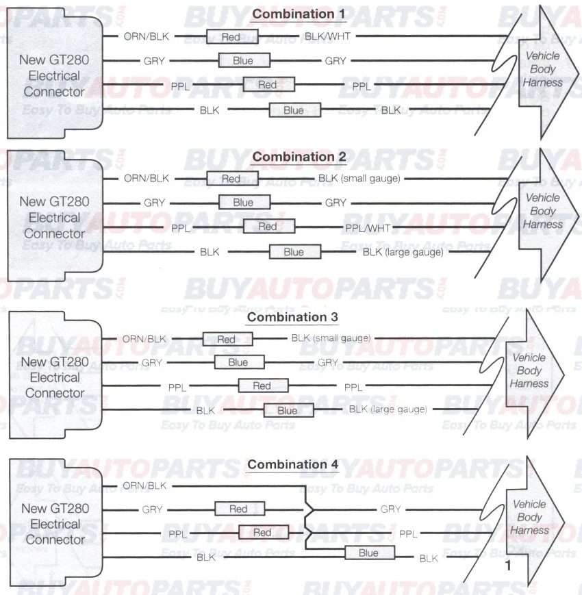
Important: Combination 4 requires the Orange/Black and Black leads from the new GT280 electrical connector to be installed into one end of a blue wire splice. Failure to do this will cause the fuel pump or fuel level sensor to operate incorrectly.
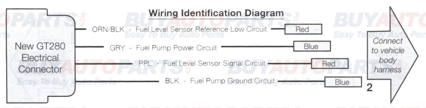
4. If the vehicle body harness wiring does not match any of the combinations shown above, refer to wiring identification diagram below (2) and the vehicle service manual or equivalent to determining the correct wiring alignment for the new GT280 electrical connector.
Installing the New Chassis Connector:
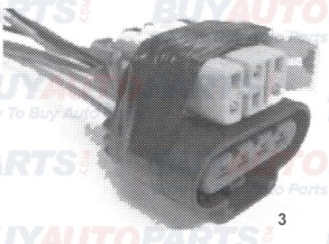
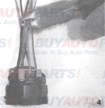
1. To assist in maintaining the approximate length of the vehicle body harness, tape the new GT280 electrical connector to the Metri-Pack 50 connector on the vehicle body harness (3).
2. Align each wire on the GT280 connector with the correct wire on the body harness and cut the wires at the desired location for the wire splice. Cut the first pair of wires 2 inches (50 mm) away from the taped electrical connectors (4) and stagger each of the cuts 1.5 inches (40 mm) longer after that. Remove the tape, and discard the original body harness electrical connector.
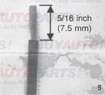
3. Remove approximately 5/16 inch (7.5 mm) of wire insulation from each of the leads on the new GT280 connector and the vehicle body harness (5).
4. Connect the new GT280 electrical connector to the body harness of the vehicle with the wire splice connectors contained in the kit. Be sure to maintain the correct wire alignment and colored wire splices as determined in step 3 or 4 of the section entitled "Determining the correct wiring combination for installing the new GT280 connector."
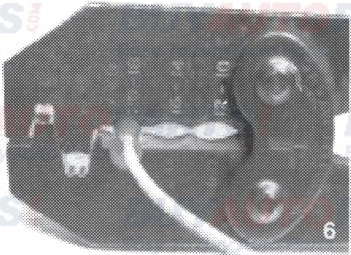
5. Crimp the splices in place with the crimp tool, Kent Moore tool J-38125-8 or equivalent (6).
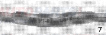
6. Shrink the insulation of the wire splices using a heat gun, until a small amount of sealant comes out of each end of the splice tubes (7).
7. Install the black plastic conduit and re-tape, as before.
8. Refer to the vehicle service manual to install the fuel sender unit on the vehicle.
